 |
| Minimum Mode Write cycle |
Sunday, February 26, 2012

Difference between MAX and MIN mode
Maximum mode
|
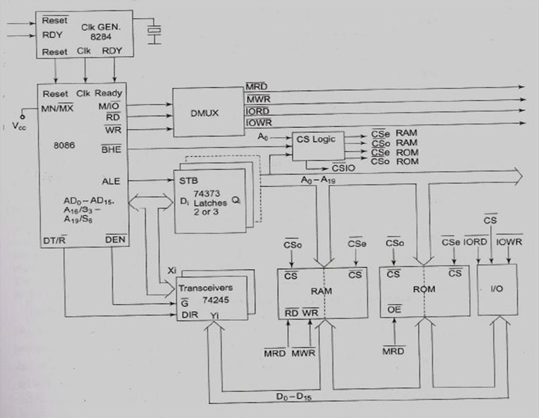
Minimum Mode
|
||||
When MN/MX(bar) low 8086 is in maximum
mode.
|
When MN/MX(bar) high 8086 is in minimum
mode.
|
||||
In maximum mode 8086 generates QS1,QS0,S0(bar),S1(bar),S2(bar),
LOCK(bar),RQ(bar)/GT1,RQ(bar)/GT0 control signals.
|
In minimum mode 8086 generates INTA(bar), ALE, DEN(bar),
DT/R(bar), M/IO(bar), HLDA,HOLD and WR(bar) control signals.
|
||||
So clearly there are multiple
processors in the system.
|
There is only one processor in the
system minimum mode.
|
||||
Whereas in maximum mode interfacing, master/slave and
multiplexing and several such control signals are required
In maximum mode a bus controller is required to produce control signals. This bus controller produces MEMRDC, MEMWRC, IORDC, IOWRC, ALE, DEN, DT/R control signals. |
In minimum mode no interfacing or master/slave signals is
required.
In minimum mode direct RD WR signals can be used. No bus controller required. A simple demultiplexer would do the job. of producing the control signals. This demultiplexer produces MEMRD, MEMWR, IORD, IOWR control signals. |
||||
|
|

Pin configuration 8086 and 8088
8086 Microprocessor
|
8088 Microprocessor
|
16 bit data bus
|
8 bit data bus
|
See Figure
 |
See Figure
 |
Has M/IO
|
Has IO/M
|
Pin Explanation
AD7-AD0 : address/data bus(multiplexed)
memory address or I/O port no : whenever ALE = 1
data : whenever ALE = 0
high-impedance state : during a hold acknowledge
AD15-AD8 : address/data bus(multiplexed)
memory address bits A15-A8 : whenever ALE = 1
data bits D15-D8 : whenever ALE = 0
high-impedance state : during a hold acknowledge
A19/S6-A16/S3 : address/status bus(multiplexed)
memory address A19-A16, status bits S6-S3
S6 : always remain a logic 0
S5 : indicate condition of IF flag bits
S4, S3 : show which segment is accessed during current
bus cycle(Table 9-4)
S4, S3 : can used to address four separate 1M byte memory
banks by decoding them as A21, A20
Function of Status bit S3 and S4
|
S4
|
S3
|
Function
|
|
0
|
0
|
Extra Segment
|
|
0
|
1
|
Stack Segment
|
|
1
|
0
|
Code or no Segment
|
|
1
|
1
|
Data Segment
|
RD(bar) : read signal
data bus receive data from memory or I/O device :RD’=0
READY :
µ enter into wait states and remain idle : READY = 0
INTR : interrupt request
used to request a hardware interrupt
if INTR is held high when IF = 1 : µ enter interrupt
acknowledge cycle(INTA’ become active) after current instruction has complete
execution
TEST(bar)(BUSY(bar)) : tested by the WAIT instruction
WAIT instruction function as a NOP : if TEST’= 0
WAIT instruction wait for TEST’ to become 0:if TEST’=1
NMI : non-maskable interrupt
similar to INTR except that no check IF flag bit
if NMI is activated : use interrupt vector 2
RESET :
µ : reset if RESET
held high for a minimum of four clock
CLK(CLOCK) : provide basic timing to µ
duty cycle of 33%
VCC(power supply) : +5.0V, ±10%
GND(Ground) : two pins labeled GND
MN/MX(bar) : select either minimum or maximum mode (HIGH
for minimum mode)
BHE(bar)/S7 : bus high enable
status of S7 : always a logic 1
BHE=0 at least one byte of current transfer is to be made
AD15-AD8 ( HIGHER ORDER BYTE)
IO/M(bar)(8088) or M/IO(bar)(8086) : select memory or I/O
address bus : whether memory or I/O port address
WR(bar) : write signal(high impedance state during hold
ack).
strobe that indicate that output data to memory or I/O
during WR(bar)=0 : data bus contains valid data for M or
I/O
Saturday, February 25, 2012
Why segmentation was done in 8086??
The segment requires only a 16 bit number to represent
the base address for a segment, and only a 16 bit offset to access any location
in a segment. This means 8086 has to manipulate and store only 16 bit
quantities instead of 20 bit quantities. This makes for an eaiser interface
with 8 and 16 bit memory boards.
Another reason is the type of micro computer in which
8086 is been likely to be used. It is made for timesharing microcomputer
system. In this several users share a CPU. The CPU works on one users program
for say 20ms then shifts to another user program say again for 20ms then it
comes back to the first user. So point is it keeps constantly switching for new
code and new data.
Segmentation makes this process of switching very easy
for processor. Each users program can be assigned a separate set of logical segments
for its code and data.
So in short segmentation makes it easy to keep users
programs and data separate from each other, making switching easy.
The pointer and index register in execution unit
The execution unit contains a 16 bit Base Pointer
register. It also contains a 16 bit Source Index register and a 16 bit
Destination Index register. These 3 register can be used for the temporary
storage of data just as the general purpose register.
Their main use is to hold the 16 bit offset of a data
word in one of the segment.
Say for example SI is used for holding the offset of data
word in data segment.
The Instruction Pointer in 8086
The code segment register holds the upper 16 bits of the
starting address of the segment from which the BIU is currently fetching the
instruction code byte.
Now the instruction pointer comes in picture. This
register is responsible for holding the 16 bit offset, of the next code byte
within this code segment.
The value contained in the IP is referred to as the
offset because this value must be “offset” from(added to)the segment base
address in code segment to produce the required 20 bit physical address sent
out by the BIU. Get it?? No. Then let’s repeat again.
Address given to processor(16 bit) – but processor smart
– see it adds lower 4bits to the 16 bit to attain 20 bit physical address – to
comprehend its smartness they created an oversmart personalty called IP – this
oversmart guy stores the 16 bit number that when added to last known
instruction address gives us a new instruction address – as BIU is IP’s boss so
he goes away with the credit leaving a super smart IP high and dry.
See example.
Say an instruction 16
bit address is 3432H.
The smart processor guess that instruction is at address
34320H. Voila he is right. But he doesn’t know where is the next address.
Here enters our hero IP. He is so smart that he knows
next instruction is at 45431H. so what he does is stores 1111H in his memory.
So when asked by BIU (his boss) where is the next
instruction. He gives him the value that needed to be added to get 45431H. yes
he gives 1111H.
So..
34320H + 1111H = 45431H.
BIU fetches instruction and provide it to the processor
for execution.
See this is how 8086 fetches instruction.
Subscribe to:
Posts (Atom)