 |
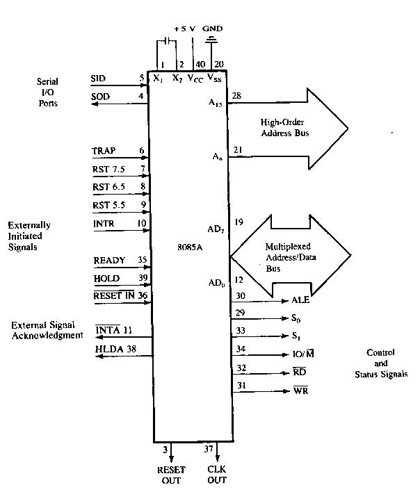
| Functional Diagram |
The 8085A uses a multiplexed Data Bus. The address is split between the higher 8bit Address Bus and the lower 8bit Address/Data Bus. During the first cycle the address is sent out. The lower 8bits are latched into the peripherals by the Address Latch Enable (ALE). During the rest of the machine cycle the Data Bus is used for memory or l/O data.
The 8085A provides RD, WR, and lO/Memory signals for bus control. An Interrupt Acknowledge signal (INTA) is also provided. Hold, Ready, and all Interrupts are synchronized. The 8085A also provides serial input data (SID) and serial output data (SOD) lines for simple serial interface. In addition to these features, the 8085A has three maskable, restart interrupts and one non-maskable trap interrupt. The 8085A provides RD, WR and IO/M signals for Bus control.
Status Information
Status information is directly available from the 8085A. ALE serves as a status strobe. The status is partially encoded, and provides the user with advanced timing of the type of bus transfer being done. IO/M cycle status signal is provided directly also. Decoded So, S1 Carries the following status information:
HALT, WRITE, READ, FETCH S1 can be interpreted as R/W in all bus transfers. In the 8085A the 8 LSB of address are multiplexed with the data instead of status. The ALE line is used as a strobe to enter the lower half of the address into the memory or peripheral address latch. This also frees extra pins for expanded interrupt capability.
Interrupt and Serial l/O
The8085A has5 interrupt inputs: INTR, RST5.5, RST6.5, RST 7.5, and TRAP. INTR is identical in function to the 8080 INT. Each of the three RESTART inputs, 5.5, 6.5. 7.5, has a programmable mask. TRAP is also a RESTART interrupt except it is nonmaskable. The three RESTART interrupts cause the internal execution of RST (saving the program counter in the stack and branching to the RESTART address) if the interrupts are enabled and if the interrupt mask is not set. The non-maskable TRAP causes the internal execution of a RST independent of the state of the interrupt enable or masks. The interrupts are arranged in a fixed priority that determines which interrupt is to be recognized if more than one is pending as follows: TRAP highest priority, RST 7.5, RST 6.5, RST 5.5, INTR lowest priority This priority scheme does not take into account the priority of a routine that was started by a higher priority interrupt. RST 5.5 can interrupt a RST 7.5 routine if the interrupts were re-enabled before the end of the RST 7.5 routine. The TRAP interrupt is useful for catastrophic errors such as power failure or bus error. The TRAP input is recognized just as any other interrupt but has the highest priority. It is not affected by any flag or mask. The TRAP input is both edge and level sensitive.
Basic System Timing
The 8085A has a multiplexed Data Bus. ALE is used as a strobe to sample the lower 8bits of address on the Data Bus. Figure 2 shows an instruction fetch, memory read and l/ O write cycle (OUT). Note that during the l/O write and read cycle that the l/O port address is copied on both the upper and lower half of the address. As in the 8080, the READY line is used to extend the read and write pulse lengths so that the 8085A can be used with slow memory. Hold causes the CPU to relingkuish the bus when it is through with it by floating the Address and Data Buses.
System Interface
8085A family includes memory components, which are directly compatible to the 8085A CPU. For example, a system consisting of the three chips, 8085A, 8156, and 8355 will have the following features:
· 2K Bytes ROM
· 256 Bytes RAM
· 1 Timer/Counter
· 4 8bit l/O Ports
· 1 6bit l/O Port
· 4 Interrupt Levels
· Serial In/Serial Out Ports
In addition to standard l/O, the memory mapped I/O offers an efficient l/O addressing technique. With this technique, an area of memory address space is assigned for l/O address, thereby, using the memory address for I/O manipulation. The 8085A CPU can also interface with the standard memory that does not have the multiplexed address/data bus.
--------------
No comments:
Post a Comment